Overview
| Information | USB 2.0 4-Port Hub (STT) |
|---|---|
| Data Bus Interface | USB 2.0 |
| Downstream Ports | 4 |
| Downstream Port disable | ✔ |
| Transaction Translator | STT |
| Bus-Powered | ✔ |
| Self-Powered | ✔ |
| Battery Charging | ✔ |
| Overcurrent monitoring | ✔ |
| Individual Port Power Management | |
| Ganged Port Power Management | ✔ |
| Supply Voltage Range VCC (V) | 3.0-3.6, 4.4-5.25 |
| Temperature Range (°C) | 0 to 70 |
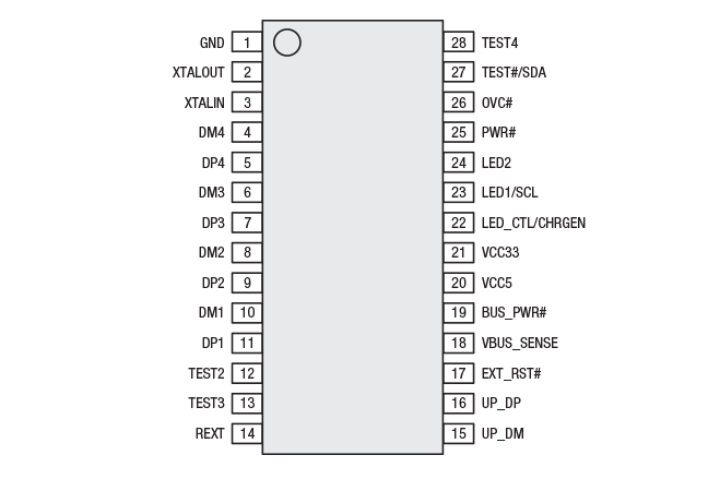
| Package | QFN-24 SSOP-28 |
The XR22404 is a USB 2.0, 4-port hub that can be configured for downstream device charging and is compatible with Battery Charging specification revision 1.1/1.2.
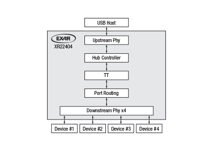
The upstream USB interface has an integrated USB 2.0 PHY and device controller that is compliant with both hi-speed (480Mbps) and full-speed (12Mbps) and downstream PHY supporting hi-speed, full-speed and low-speed (1.5 Mbps) on each of the 4 downstream ports.
The XR22404 provides ganged power control and global overcurrent sensing for the downstream ports.
The XR22404 may be operated from either 5V or 3.3V. If powered from 5V internal regulators provide 3.3V and 1.8V used internally by the device. Port activity and overall hub activity indicators provide status outputs for external LEDs. An external I2C EEPROM may be used with the XR22404 to configure USB device descriptors.
- USB 2.0 compliant interface
- Provides downstream port battery charging
- LED indicators for port, hub or charging activity
- Global port power enables
- Ganged overcurrent sensing
- Single 5V or 3.3V power supply
- Single 12MHz Crystal
- USB port expansion
- Docking stations
- POS terminals
- Factory automation and process controls
- Industrial applications
Documentation & Design Tools
| Type | Title | Version | Date | File Size |
|---|---|---|---|---|
| Data Sheets | XR22404 USB 2.0 4-Port Hub | 1B | September 2018 | 524.5 KB |
| User Guides & Manuals | XR224xx USB Hub Design Guide | 00 | April 2020 | 2.3 MB |
| User Guides & Manuals | XR22404 Evaluation Board User’s Manual | Rev 1B | July 2017 | 457.7 KB |
| Product Flyers | USB Hub Controller Flyer | March 2019 | 1.5 MB | |
| Schematics & Design Files | Evaluation Board Schematic | 1.1 | July 2017 | 37.3 KB |
| Schematics & Design Files | XR22404 Eval Board & Schematic, BRD, RSN Files | 1.1 | July 2017 | 462.9 KB |
Quality & RoHS
| Part Number | RoHS | Exempt | RoHS | Halogen Free | REACH | TSCA | MSL Rating / Peak Reflow | Package |
|---|---|---|---|---|---|---|---|
| XR22404CL24TR-F | N | Y | Y | Y | Y | L3 / 260ᵒC | TQFN24 4x4 |
| XR22404CG28TR-F | N | Y | Y | Y | Y | L3 / 260ᵒC | SSOP28 4x10 |
Click on the links above to download the Certificate of Non-Use of Hazardous Substances.
Parts & Purchasing
| Part Number | Pkg Code | Min Temp | Max Temp | Status | Suggested Replacement | PDN |
|---|---|---|---|---|---|---|
| XR22404CG28-F | SSOP28 4x10 | 0 | 70 | OBS | ||
| XR22404CG28TR-F | SSOP28 4x10 | 0 | 70 | OBS | ||
| XR22404CL24-F | TQFN24 4x4 | 0 | 70 | OBS | ||
| XR22404CL24TR-F | TQFN24 4x4 | 0 | 70 | OBS | ||
| XR22404CG28EVB | Board | OBS | ||||
| XR22404CL24EVB | Board | OBS |
Active - the part is released for sale, standard product.
EOL (End of Life) - the part is no longer being manufactured, there may or may not be inventory still in stock.
CF (Contact Factory) - the part is still active but customers should check with the factory for availability. Longer lead-times may apply.
PRE (Pre-introduction) - the part has not been introduced or the part number is an early version available for sample only.
OBS (Obsolete) - the part is no longer being manufactured and may not be ordered.
NRND (Not Recommended for New Designs) - the part is not recommended for new designs.
Packaging
| Pkg Code | Details | Quantities | Dimensions |
|---|---|---|---|
| SSOP28 4x10 |
|
|
|
| TQFN24 4x4 |
|
|
|
Notifications
FAQs & Support
Search our list of FAQs for answers to common technical questions.
For material content, environmental, quality and reliability questions review the Quality tab or visit our Quality page.
For ordering information and general customer service visit our Contact Us page.
Submit a Technical Support Question As a New Question
With a plethora of equipment with built in USB ports, USB hubs assist by expanding the number of USB ports available to plug devices into in a network. In its simplest form, a USB hub is plugged into a host computer’s USB interface. A hub has one upstream path (going back towards the host’s USB interface) and multiple downstream paths (going towards the end devices). Another downstream hub could be plugged and cascaded into the first hub and so on up to 7 tiers and 127 ports. There are limitations on USB cable length, however a USB hub can function as a repeater if more length is needed. See AN213 section 3.0 for more information.
USB is governed by industry specification http://www.usb.org/developers/docs/usb20_docs/ .
MaxLinear XR22404 and XR22414 USB hubs have 4 available downstream ports while the XR22417 provides 7. All 3 parts have a USB 2.0 compliant interface, meaning that the upstream is capable of high speed (480Mbps) and may operate at high (480Mbps) or full speed (12Mbps). Downstream can operate and high (480Mbps), full (12Mbps) or low speed (1.5Mbps).
USB 2.0 host ports provide up to 5 unit loads of 100 mA per attached peripheral device (including USB hubs). A bus powered hub, powered from USB host 5 volt VBUS, can supply a maximum of 1 unit load on each of its downstream ports. For example, a 4-port hub must be able to supply 4 x 100 mA or 400 mA total and is also allotted 100 mA for its own power requirements. A hub with more than 4 downstream ports cannot be bus powered.
Conversely, a self-powered hub is powered by an outside power source. It is restricted in the number of downstream ports and the power to those ports only by the power from the external source. A self-powered hub should typically be able to provide a minimum of 5 unit loads per downstream port.
MaxLinear has a number of USB 2.0 hub products. The 4-port XR22404, XR22414 and 7-port XR22417 all support self-powered mode while XR22404 and XR22414 can also be bus-powered. The XR22404 can provide battery charging on its downstream ports, but must be in self-powered mode to do so.
STT (Single Transaction Translator) is where one TT splits transactions and polls round robin to translate to multiple downstream peripheral devices, such as in the case of the XR22404 that shares the bandwidth. MTT (Multiple Transaction Translator) is where several are provided. The XR22414 provides one for each of the 4 downstream ports, while the XR22417 provides one for each of the 7 downstream ports. A dedicated TT for the downstream ports provides each the highest bandwidth capability, 12Mbps each in the case of full speed.


Either an individual or ganged power mode can be employed. In ganged mode all ganged ports are monitored by one power monitoring device and global current sensing is used. However in an over-current condition, all ganged ports are disabled. In individual mode each downstream port monitors over-current and can disable power independently. XR22404 uses ganged power mode and global overcurrent sensing. XR22414 can be configured for either ganged or individual power mode as shown in its datasheet. XR22417 uses individual power mode.
The hub then signals the USB host and the host marks the port. SP2525A or SP2526A can be used in conjunction with the XR22404, XR22414 and XR22417 devices.
Find the product page of the part that you want to get an evaluation board for and click on Parts & Purchasing. Example:
Click on Parts & Purchasing or Order Now. Locate the icons under Buy Now or Order Samples:
Click on the Buy Now icon and see who has stock and click on the Buy button:
Alternatively, you can click on the Order Samples icon to request a sample.
Note, not all products are sampleable from the website.
If the icons are missing, create a support ticket.
https://www.exar.com/quality-assurance-and-reliability/lead-free-program
Visit the product page for the part you are interested in. The part's status is listed in the Parts & Purchasing section. You can also view Product Lifecycle and Obsolescence Information including PDNs (Product Discontinuation Notifications).
To visit a product page, type the part into the search window on the top of the MaxLinear website.
In this example, we searched for XR33180. Visit the product page by clicking the part number or visit the orderable parts list by clicking "Orderable Parts".
The Parts & Purchasing section of the product page shows the Status of all orderable part numbers for that product. Click Show obsolete parts, to see all EOL or OBS products.
USB peripheral devices may operate in bus or self-powered modes. In bus powered mode, the peripheral device is powered by the USB host 5V VBUS power either directly, or for example through a voltage regulator that might provide a regulated 3.3V to the device from the 5V VBUS input. In self-powered mode, power to the peripheral device comes from another source other than the USB host VBUS. For example, power might come from an AC to DC converter.
MaxLinear USB to serial / UART(s), USB hubs and USB to Ethernet devices all comply fully to USB standards and are fully USB compliance tested. One USB compliance test ensures that self-powered peripheral devices do not have “back voltage” when disconnected from the USB host, on either the USB data signals (USBD+ / USBD-) or the VBUS power itself.
All MaxLinear USB UARTs, hubs and USB to Ethernet devices are USB full speed or high-speed devices. As such, they have an internal pull-up on the USBD+ signal to “advertise” their speed rating. The VBUS_SENSE pin on these devices must be connected to VBUS from the host, or upstream device if that is not the host, such that the device “senses” the disconnection from the host or upstream device. The default power mode advertised to the USB host for all USB UARTs and USB to Ethernet devices is bus powered mode. Self-powered mode can be programmed in either the internal OTP memory or external EEPROM for self-powered mode. For MaxLinear hubs, an external pin controls the power mode advertised to the USB host, except the XR22417 which must always be operated in self-powered USB mode.


